

The principle of operation of the roller brake and its device
Introduction
Before you start viewing this article, I recommend that you look at overview of the Shimano BR-IM55-F roller brake.

Hello, dear visitors. At one time, after buying a roller brake, I was puzzled by the search for information about roller brakes and found out that there is not so much information on this topic in the Runet, I would even say very little. For example, I didn’t find anything at all about disassembling my particular brake model — Shimano BR-IM55-F. Most of the available information is focused on forums where people share not always verified data, and sometimes even rumors. For example, I have met several times a description of the operation of the roller brake, where someone told that the principle of the roller brake, as he understands, is supposedly the friction of the rollers, which is completely wrong. And I’m almost sure that the person who came up with this idea has never seen these rollers indeed. In addition, there are many rumors about the design of these brakes, their lubrication, and so on, for example, I have met statements that roller brakes are absolutely sealed and can be lubricated with liquid oil. After reading all this, I realized that as the owner and user of the roller brake, I must share reliable information. I tried to collect as much detailed information as possible, describe and show my roller brake in all the details. With this article, I want to dispel most of the rumors that go around this type of brakes. Are you interested in finding out how roller brakes actually work, what they are made of, and what it all looks like? Read more about all this in my article.
The principle of operation of the roller brake on the example of Shimano BR-IM55-F
To begin with, let me describe the principle of operation of the roller brake in words, this will apply to all models. After I show a small visual diagram and then consider the principle of operation on the example of a specific model that I use myself personally-the front roller brake Shimano BR-IM55-F.

So, the principle of operation of the roller brake is similar to the operation of the drum brake. I would even say that their principles of work are fundamentally no different. The only difference is that the roller brake uses a different principle of transferring the brake force to the pads. Let’s get into the details, how does this happen? When the cyclist presses the brake handle / lever located on the handlebar, it in turn pulls the cable, the opposite end of which drives the eccentric lever inside the roller brake. This eccentric lever has a special shape (like a flower) and when rotating, its protrusions rest on the rollers, the rollers in turn press on the pads, bursting them, and they rest on the working surface of the brake drum, slowing down its rotation. Since the roller brake drum is directly connected to the wheel hub by splines, the rotation of the bicycle wheel itself slows down. This is how braking occurs.
Now I will note a few points. First, the roller brake is lubricated. Despite the fact that the lubricant on the contrary reduces the friction force of the pads on the brake drum, braking is still carried out due to the high pressure force of the pads on the brake drum. Due to the high pressure, the pads squeeze out some of the grease from under them, but the thinnest layer of grease between the pads and the working surface of the brake drum still remains, which reduces the wear of both the pads and the working surface of the brake drum. At the same time, a huge amount of heat is released, which is removed by a radiator (cooling fin) pressed on the brake drum. Early models of roller brakes did not have a separate radiator, in them the cooling function was performed by the brake drum itself directly. Secondly, on the Internet you can find a description of the operation of the roller brake, which indicates that the braking is carried out by friction and rotation of the rollers. This is not true. The rollers do not participate in the friction process, but only transmit the force to the pads. That is why the brake is called a roller (roller) — because the rollers are used to transfer the force to the brake pads.
Let’s move on from the words to the diagram, everything that I described just above is very well displayed on it. The scheme is of course extremely simplified, it shows only the most basic elements of the design of the roller brake, but it clearly shows the principle of operation of the roller brake. The principle of operation shown in the diagram is applicable to all models of roller brakes. The diagram shows the following brake elements: a drum (outer ring), three brake pads, six rollers and an eccentric:

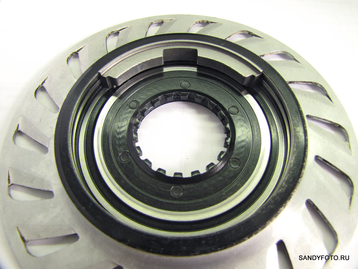
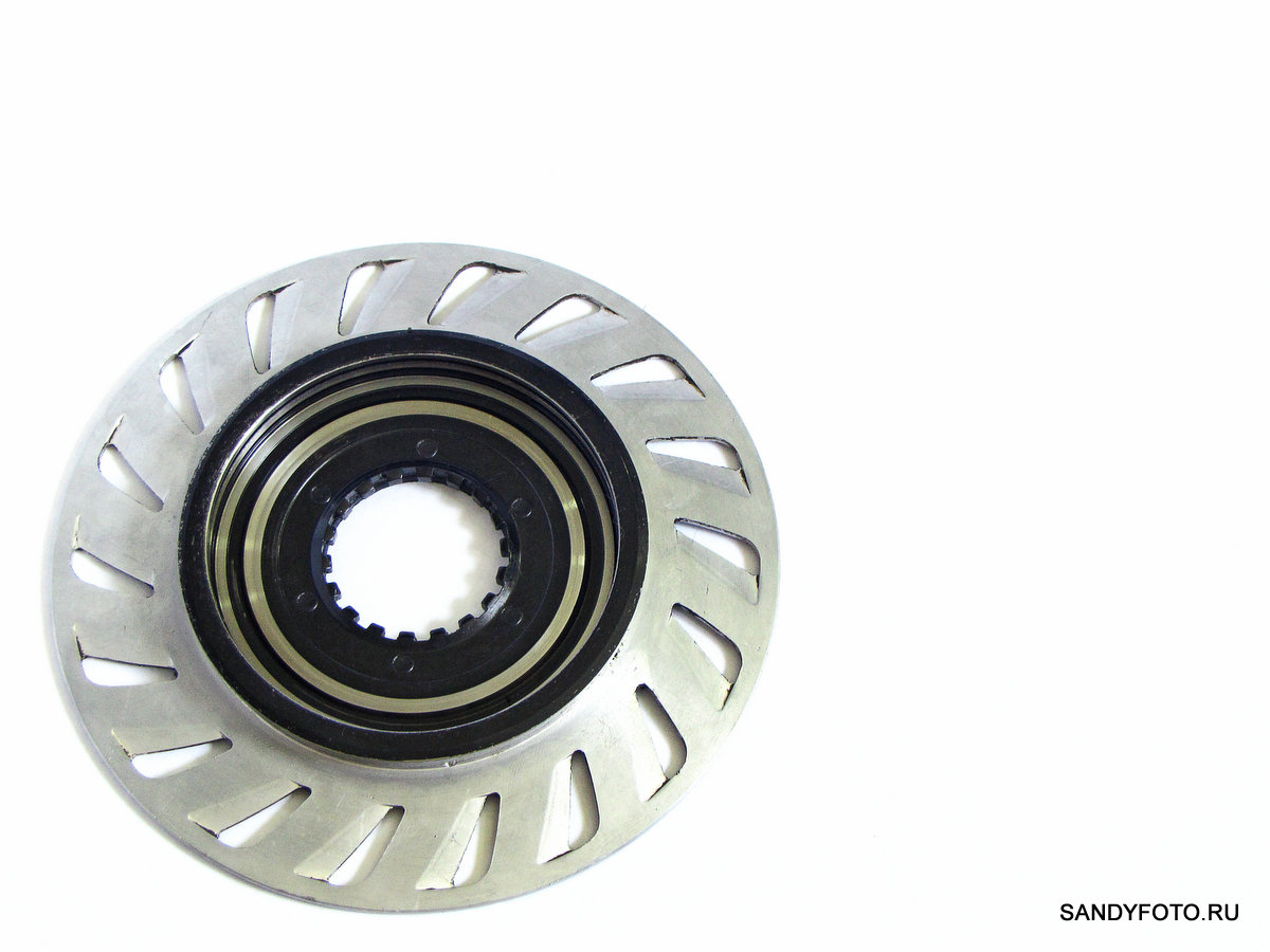
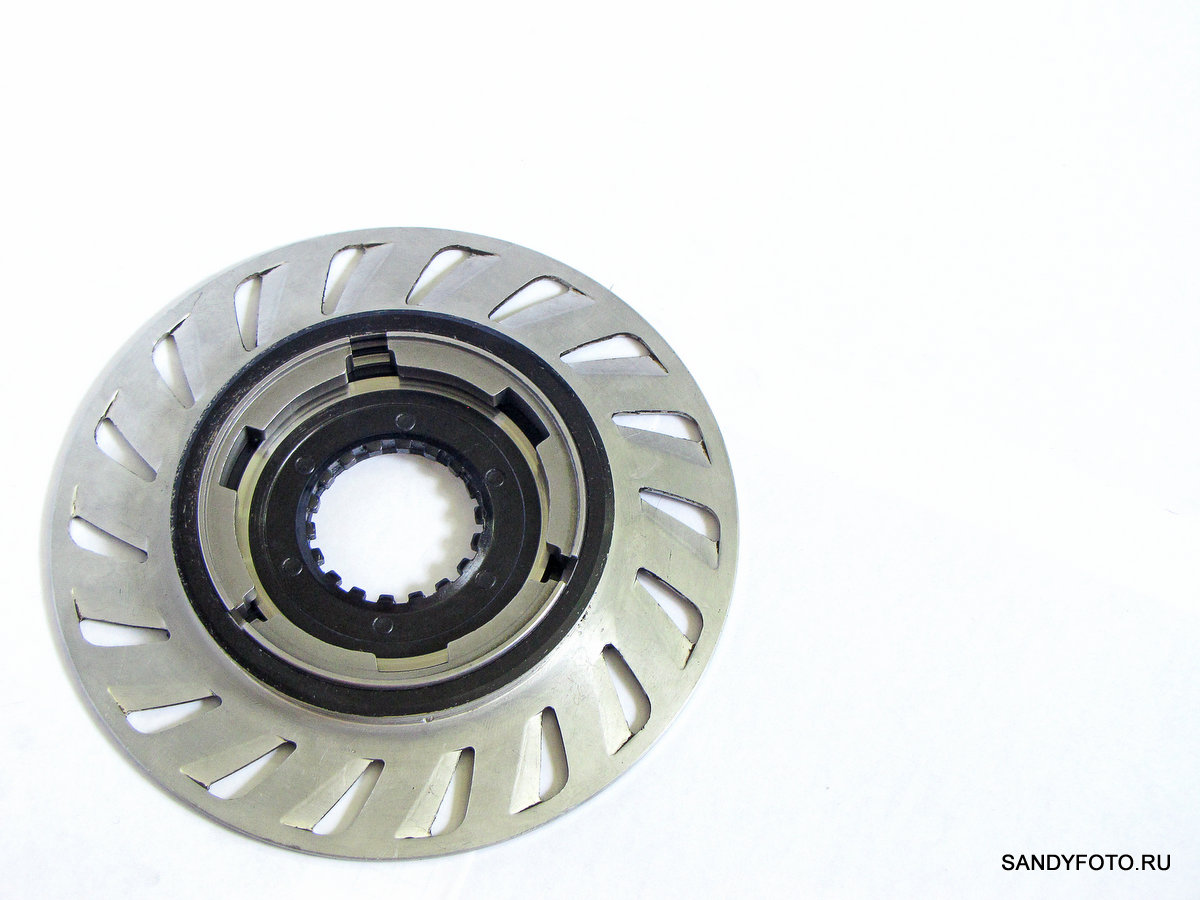
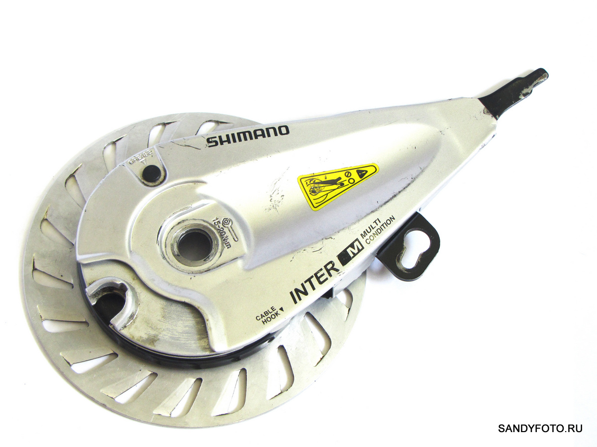
Now let’s look at the principle of operation on the example of a specific model-the front brake Shimano BR-IM55-F. This is how this model looks assembled, removed from the wheel:

When the cyclist performs braking, the cable pulls the eccentric lever inside the brake. The lever is driven by a separate part. The direction of movement of the lever is indicated by a red arrow. The blue arrows indicate the direction of rotation of the brake drum while the bike is moving:

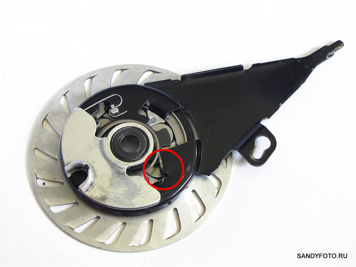
Let’s see what happens at this moment inside the brake. To do this, remove the brake cover and remove the parts that interfere with the view. Inside the brake, the following happens: the eccentric lever moves and protrusions rest on the rollers, which press on the brake pads, they in turn rest on the working surface of the rotating brake drum. The blue arrows indicate the direction of rotation of the brake drum, the red arrows indicate the movement of the eccentric lever, the green arrows indicate the direction of movement of the rollers:

For greater clarity, I show the same thing, but without the eccentric lever

Roller brake device
We will also consider the device of the roller brake on the example of a specific model — Shimano BR-IM55-F. Of course, different models of roller brakes differ in their structure, but, nevertheless, the principle of operation and the basic elements of different models of these brakes are similar. For your convenience, I disassembled the brake into its component parts, spread it out on white paper and photographed it in one frame. After you have numbered each part, see the description of the parts under the photo. As you can see, the model of the front roller brake Shimano BR-IM55-F consists of ten elements:

- A cover that performs a decorative and protective function, it has a lubricating hole that is closed with a rubber stopper;
- The part that transfers the force from the cable to the eccentric lever;
- Return spring of the eccentric lever;
- Return spring of the cage with rollers;
- The basis of the roller brake, the power element that takes on the entire load. It is this part that ensures the immobility of the brake pads and prevents them from turning. To ensure the operation of the brake, the shank of this part is fixed to the fork of the bike with a clamp. Is a non-separable part;
- Lever-eccentric;
- Rollers in the amount of six pieces, two for each brake pad;
- The clip into which the rollers are inserted is necessary for positioning the rollers relative to the pads and the eccentric lever;
- Brake pads in the amount of three pieces;
- The brake drum with the radiator pressed on it is an unassembled part;
- A tube of branded lubricant for Shimano roller brakes. It is not an element of the design of the brake, it is only present in the photo for the entourage. See the mini-review of this lubricant at this link;
Let’s look at each detail separately and from different angles. Further in the text in parentheses, I will indicate the number under which you will find this detail in the list and in the general photo, all for your convenience = ) In the description of the details, I use the concept of «external side». The outside side refers to the view from the side of the wheel where the roller brake is installed.
Cover (1), top view, in the left part you can see the lubrication hole, closed with a black plug:

Cover (1), side view:

Cover (1), view from the back (inside) sides:
Grease hole closed with a plug, close-up, view from the inside of the lid:

The part (2) that transfers the force from the cable to the eccentric lever (6). This part has a connector (at the bottom of the photo), where the boss is inserted, which is fixed to the cable:

The same part (2), on the reverse side. On the left, you can see the groove for the eccentric lever (6), on the right, the stop for installing the return spring (3) of the eccentric lever:

The same part (2), view from a different angle, larger:

The same part (2), the connector where the boss attached to the cable is inserted. To the right of the connector, you can see the groove where the cable is laid:
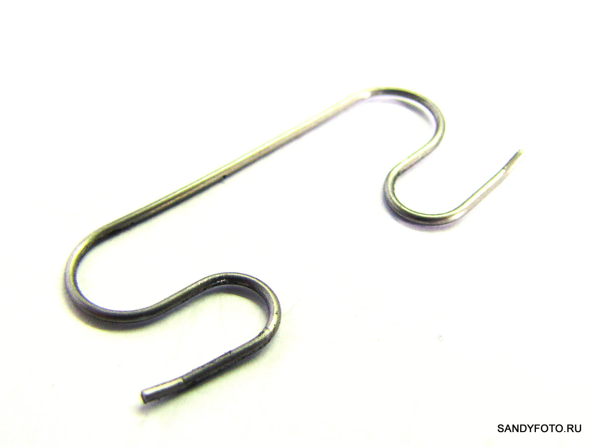
Return spring (3) of the eccentric arm (6):
Return spring (3) of the eccentric lever (6), from a different angle:

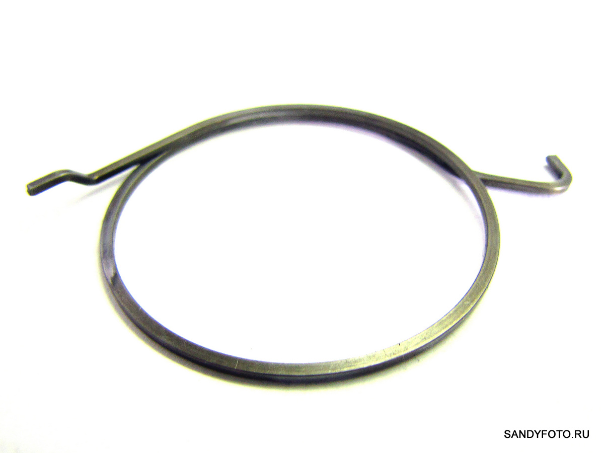
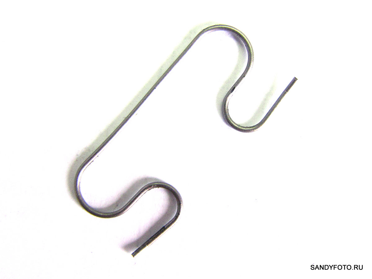
Return spring (4) Roller clips (8):
Return spring (4) roller clips (8), top view:
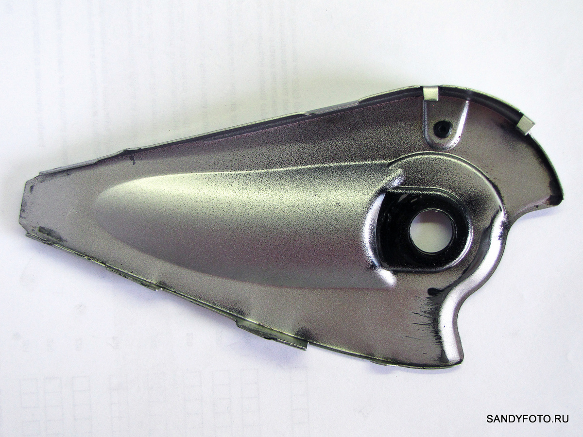
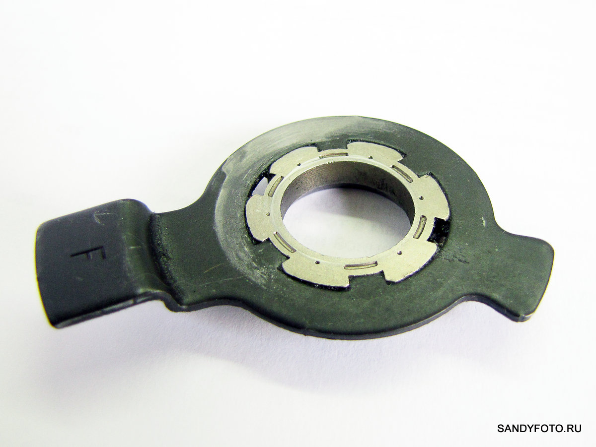
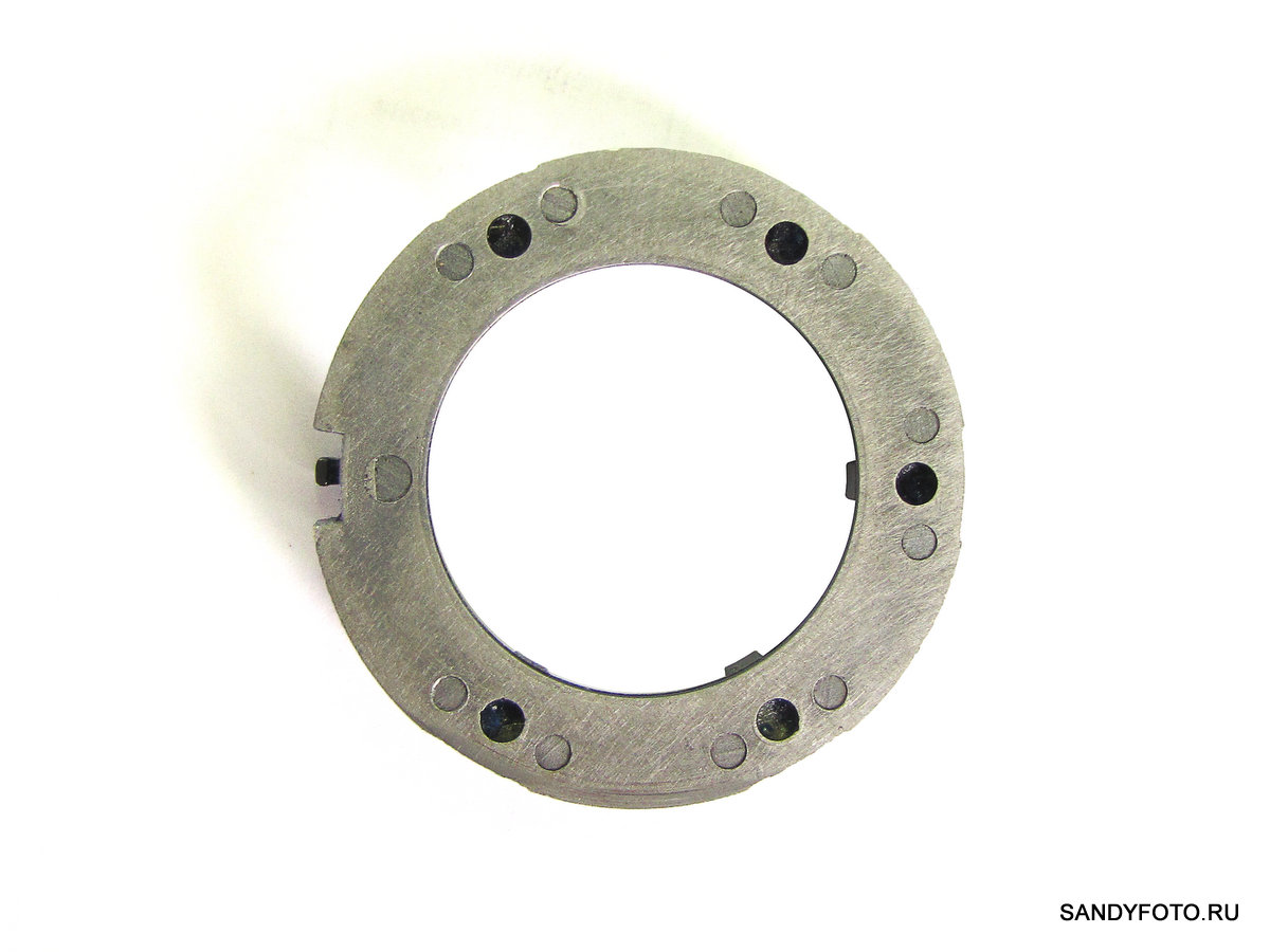
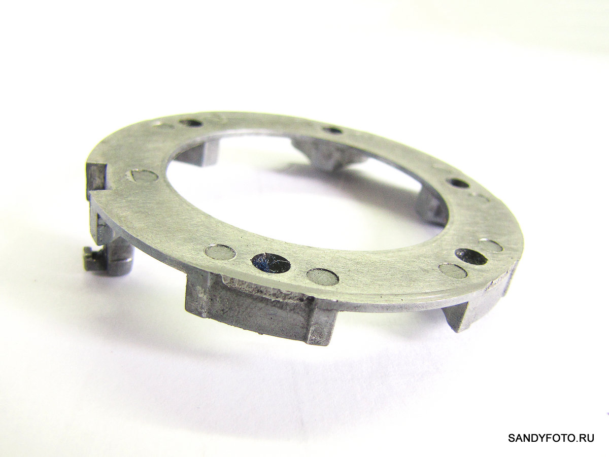
Roller brake base (5), external view:

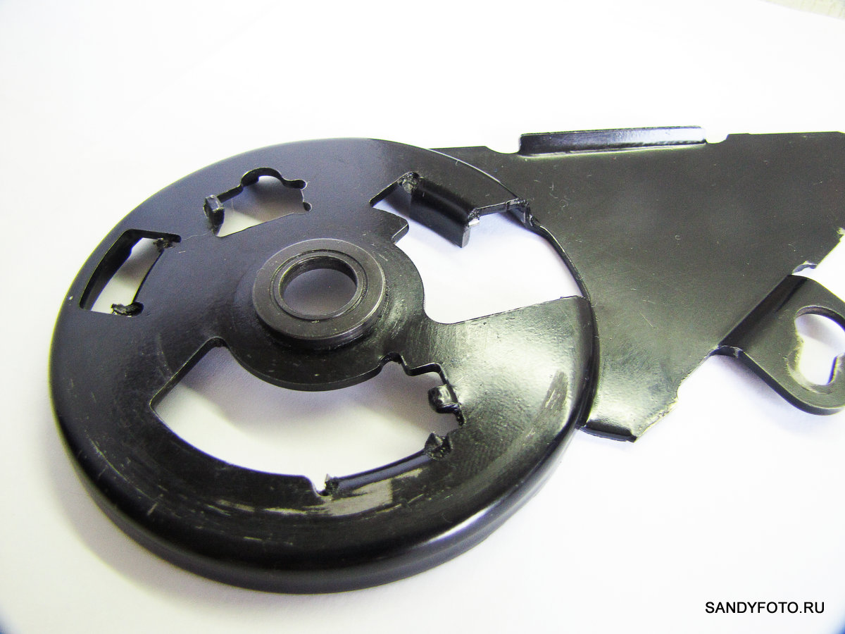
Roller brake base (5), inside view:
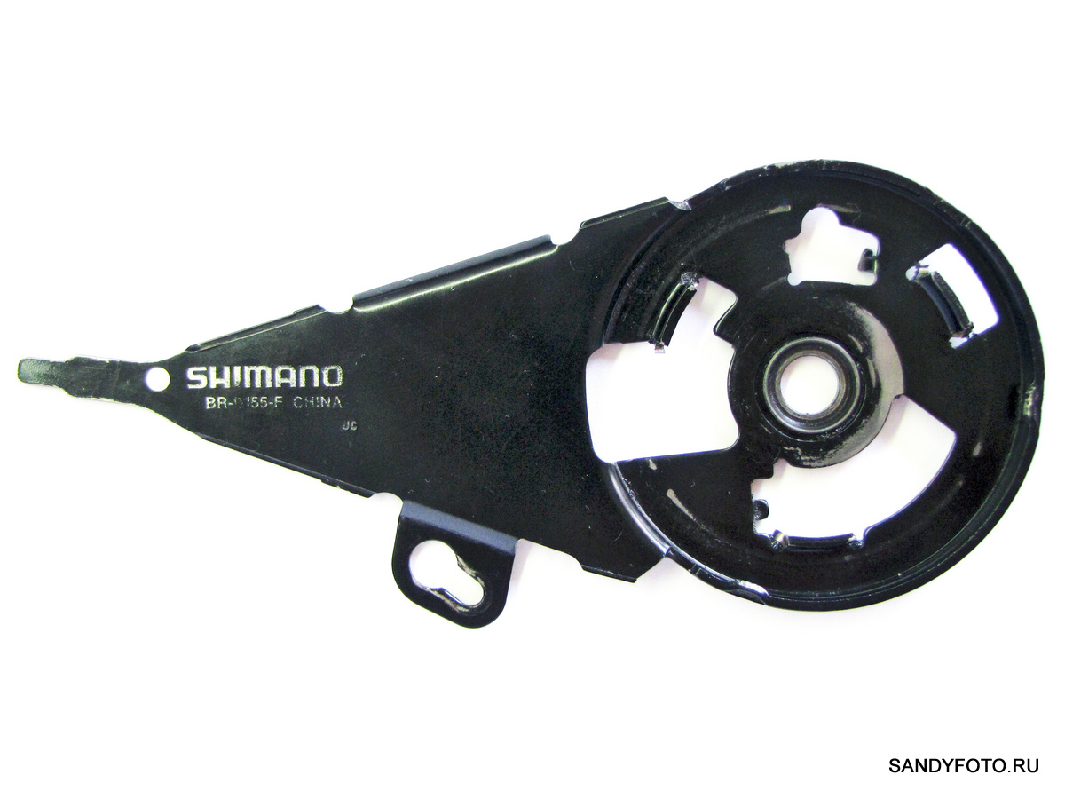
The outer side of the base (5) close-up:
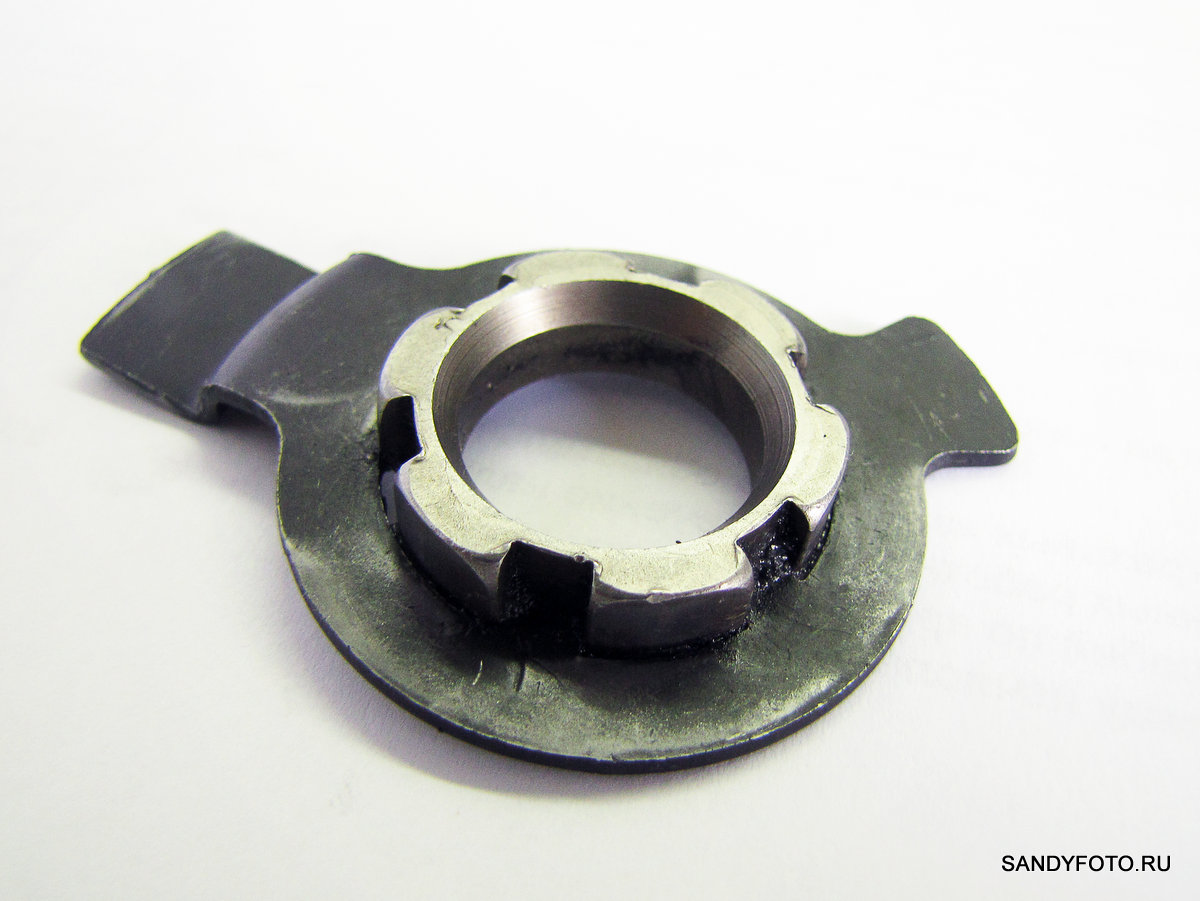
Outside of the base (5) close-up, different angle:

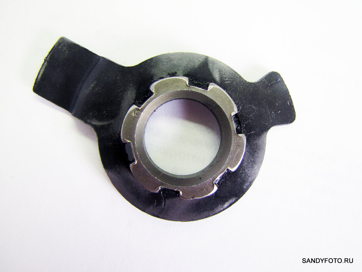
Inner side of the base (5) close-up:
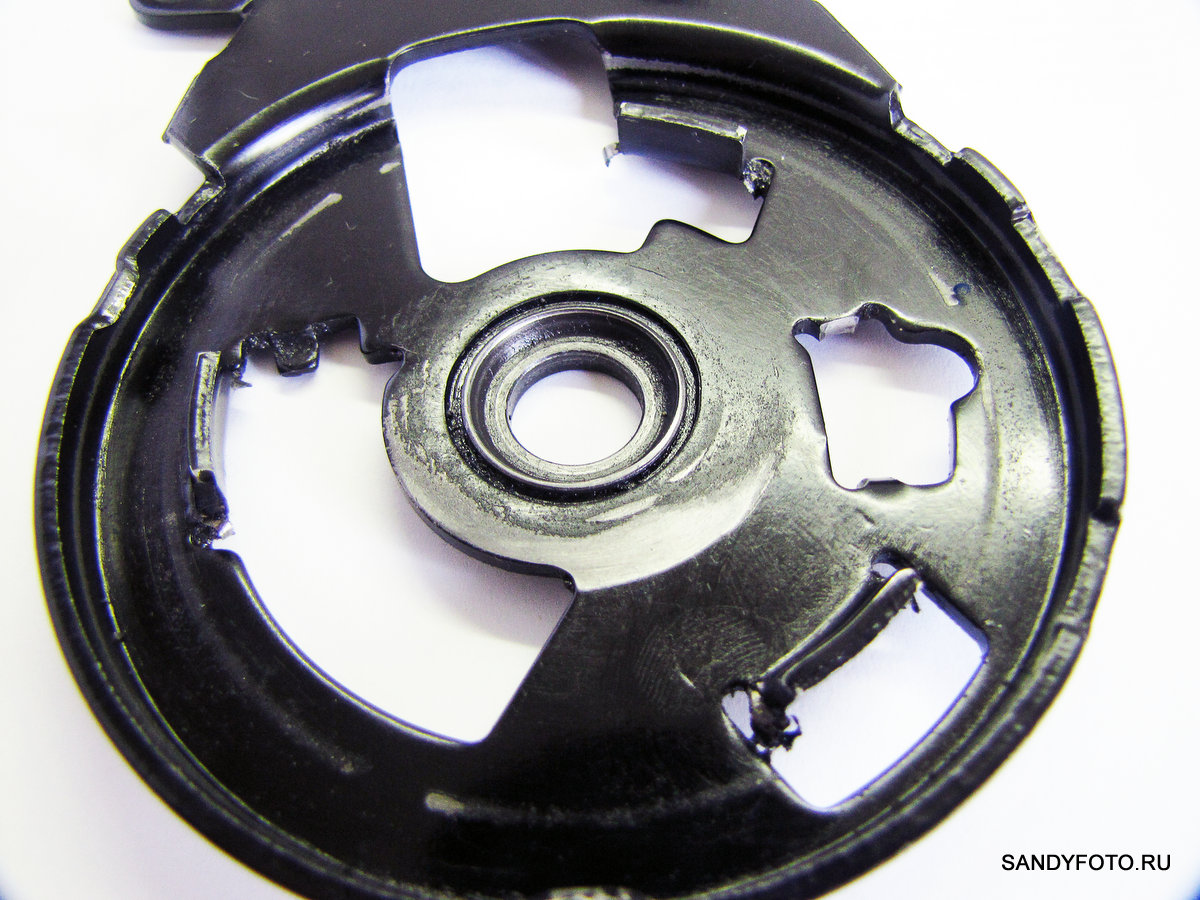
Inner side of the base (5) close-up, different angle:

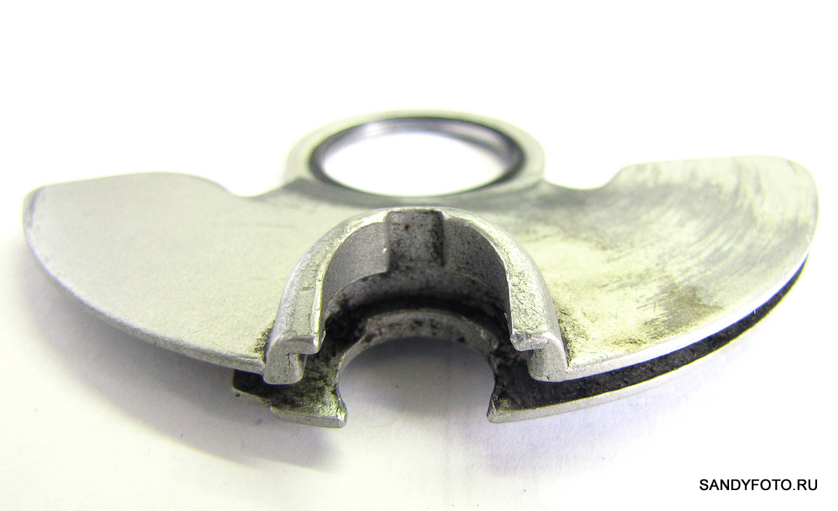
Lever-eccentric (6), top view, from the outside:

Lever-eccentric (6) close-up:
Lever-eccentric (6) close-up, different angle:

Lever-eccentric (6), view from the back, inside. It is these protrusions that put pressure on the rollers when turning the eccentric lever:
Lever-eccentric (6), view from the back, inside, other angle:
Lever-eccentric (6), another angle:

Rollers (7) in the amount of six pieces:

The rollers (7) are the same on both sides:

Rollers (7) close-up:

Roller clip (8), top view, outside view:

Roller clip (8), view from a different angle:
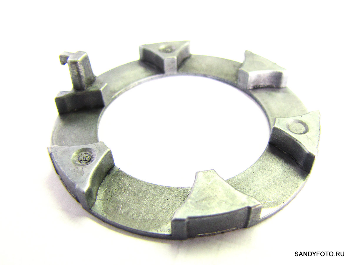
Roller cage (8), the projection where the return spring of the cage (4) is installed):

Roller clip (8), inside view:
Roller clip (8), another angle:
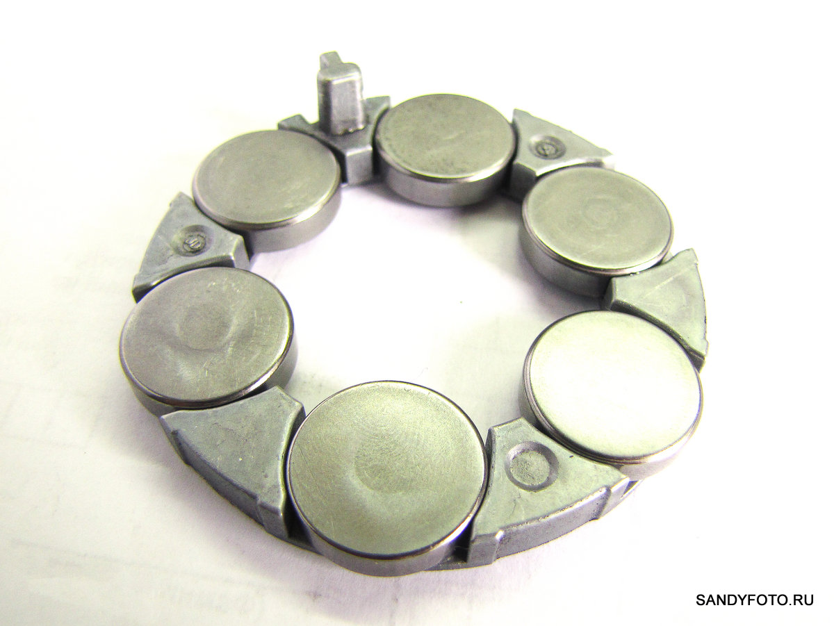
Roller holder (8) with inserted rollers (7), top view, outside:
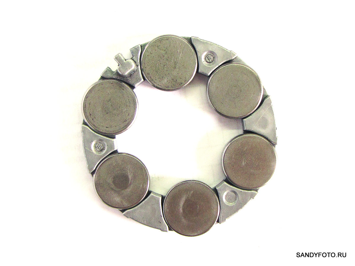
Roller clip (8) with inserted rollers (7), different angle:
Brake pad (9), top view, outside view:

Brake pad (9), rear view. This side of the pad is facing the drum:
The working surface of the brake pad (9) after approximately 3,100 km of operation, this side of the pad faces the working surface of the brake drum (10):

Brake pad (9), view from the side where the rollers are pressed (8), in the photo you can see the marks in the places of pressure of the rollers:

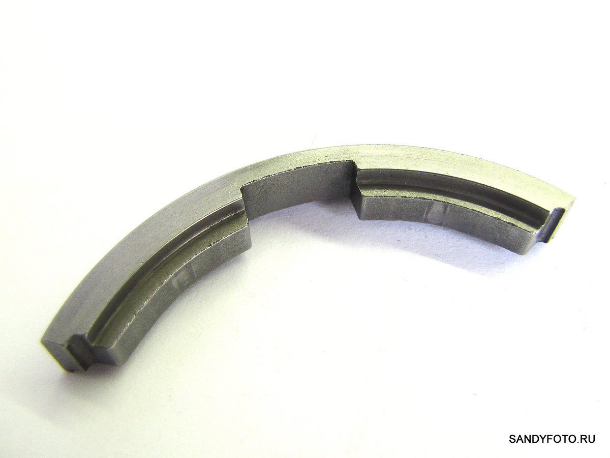
Brake drum (10) with radiator pressed on it:

Brake drum (10), reverse side:

Brake drum (10), view from a different angle:

Reverse side of the brake drum (10), different angle:
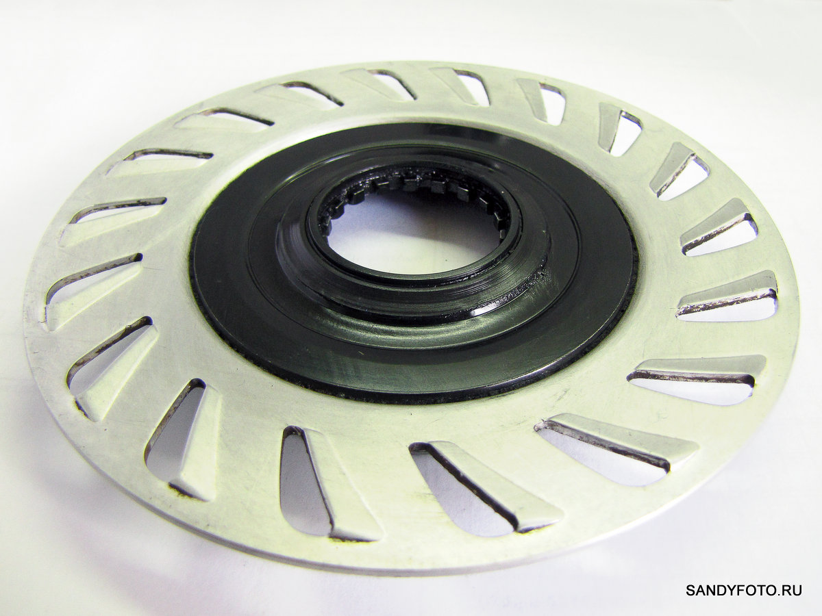
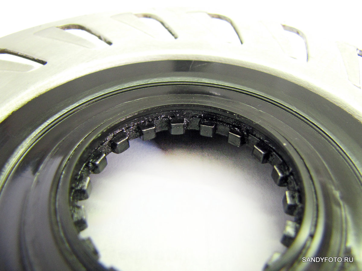
Close-up slots:
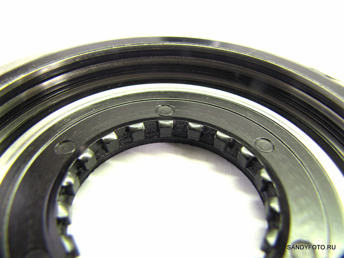
Close-up slots, view from the back of the drum:
Working surface of the brake drum (10). As you can see, there are two grooves on the working surface, they are needed for the waste of grease:

Brake drum (10) with installed brake pad (9) for better visibility:

Brake drum (10) with installed brake pad (9), different angle:
We have just reviewed all the components of the front roller brake Shimano BR-IM55-F in every detail. We proceed to disassembly and assembly.
Disassembly and assembly of the roller brake
I couldn’t find any instructions on disassembling my particular model of roller brake on the Internet — Shimano BR-IM55-F (relevant at the time of this writing). So my instruction will be the first.
The design Shimano BR-IM55-F is extremely simple, so I do not think that anyone can have problems with disassembling this brake. The only point with which the question may arise is the removal of the lid.
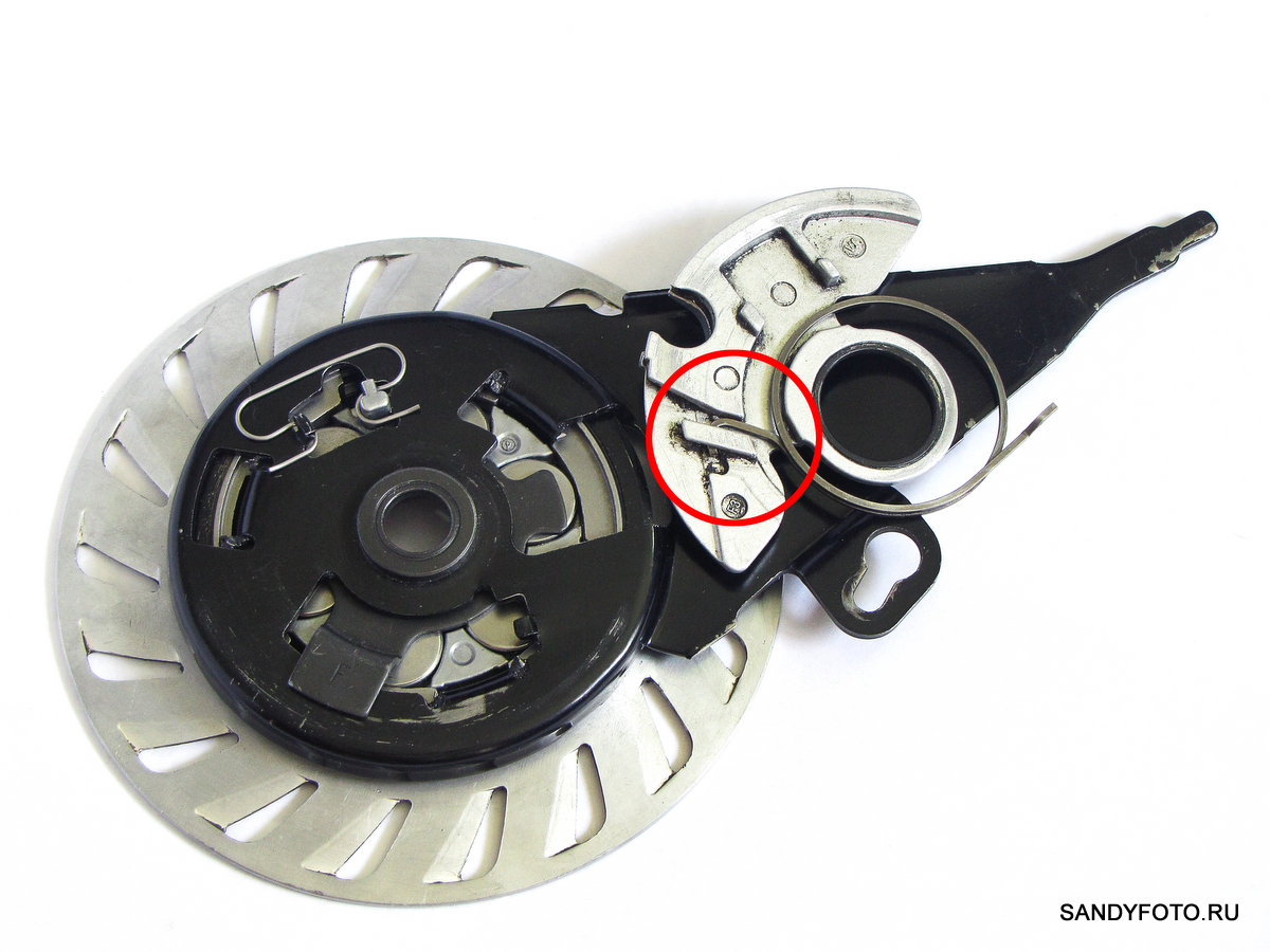
To remove the lid, insert a screwdriver and gently pry the lid, sliding it sideways and up. I show it in the photo. The place where you need to insert the screwdriver is marked in red:

Everything else is extremely easy and simple to disassemble, but it may be a little more difficult to assemble. To do this, I filmed the assembly process in stages. I show you.
So, take the brake drum (10):
Then install the three brake pads (9) in such a way that there is an equal space between them:
Then install the clip (8) with the rollers (7) so that the protrusion of the clip is directed into the empty space between the pads:

Now you need to insert the eccentric lever (6) so that it is rotated approximately a little more than 90 degrees counterclockwise relative to the protrusion on the clip (8) with the rollers:

The next step is to install the base (5). It must be installed in such a way that the three projections on the base (5) coincide with the corresponding grooves in the three pads (9), to do this, rotate the base in different directions until you catch the desired position. Then insert the base (5) until it stops. Note that the eccentric lever (6) must pass through the window allocated for it in the base and lie on top of it, and the protrusion of the roller cage (8) must also pass into the slot allocated for it in a curly shape:

We proceed to the installation of the return spring (4) of the clip (8). One end of this spring should stand in the protrusion of the clip, and the other in the protrusion assigned to it on the base (5):

Next, install the return spring (3) on the part (2) that transfers the force from the cable to the eccentric lever (6). To do this, install the L-shaped end of the return spring (3) in the special stop of the part (2) as shown in the photo:
Then you need to install the part (2) on the base (5). In this case, the straight end of the return spring (3) should stand in the corresponding protrusion on the base (5), and the eccentric lever (6) in the corresponding groove of the part (2):
The final step is to install the cover (1). If the cover does not snap, make sure that the return spring (3) of the eccentric lever does not interfere with the installation of the part (2). So we got the brake assembly:
As you can see, the design of the brake is extremely simple and tightness here does not even smell. Therefore, the roller brake can not be lubricated with liquid grease, due to the fact that it will simply flow out of there.
If any of you have any problems with the assembly, I can post even more detailed photos with color markings for maximum clarity. If necessary, write in the comments.
This concludes, thank you for your attention!
That’s a very comprehensive review indeed! I use the roller brakes throughout maybe 7 years already so there’s basically nothing new to me to know anymore but I wish I had this article like 5 years ago, it would have saved me a lot of time. Still, as I’ve browsed through your site and found out that the brake you bought didn’t serve you well, which is a pity to know, yet my experience says that the less attention you show to these brakes the better they work:) I didn’t even grease them more often than once in a year and the only reason that made me once to open one of my brakes up was my curiosity — and here’s where I’d have needed this article so badly. Anyway, thank you for the awesome work you are doing, you have a nice blog!
Thank you for a nice comment! I’m glad that your roller brake operating well all of these years. I was not so lucky with my brake.